Ok, first of all, for those of you who have not had the opportunity to examine the F2 and the FE cylinder head we will start off with some basic pictures and description. Below are several pictures that should give you a good reference.
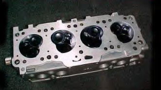
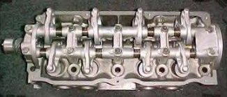
The head is a very basic design for the most part. There are two valves per cylinder, one intake and one exhaust. The casting is made from aluminum and it is an overhead cam design. The cam journals ride directly on the cylinder head in an area machined to function as a bearing surface. These heads came with both mechanical and hydraulic shaft mount rocker arm assemblies depending on the make and year of the truck. This system has 5 caps which not only have the bearing surface but also support the rocker shafts and provide all the oiling for the valve train. The head uses 8 mm stem valves and dual valve springs. Seals for the camshaft are at each end, one fits in the distributor housing and the other is in the back and held in by crush from the end cap.
Now for more complicated stuff. The Mazda factory manual refers to the combustion chamber design to be Multi-spherical which would commonly be called the “twisted wedge” design. Basically this design mimics the power and efficiency of a Hemi design yet still provides fuel efficiency and emissions of other designs. This chamber design can be identified by a sort of heart shape look and usually every pair side by side is twisted to face each other. The valves are canted (angled) this allows the valve to move farther away from the cylinder wall as it opens which increases its flow ability. The intake valve and exhaust valves are on opposite sides of the combustion chambers and the ports lead in one side and out the other. This is called a cross-flow design; it keeps the air moving in the same direction which increases performance. Think of it like driving, if an intersection is the cylinder it is faster to go straight through than to stop and do a U-Turn. This also helps by keeping the exhaust manifold on the other side of the engine from the intake which keeps it cooler. The chamber volume to surface area ratio is relatively low with a volume of about 60 cc. This confines combustion to a smaller area which greatly decreases burn time, because of this less timing advance is required and it allows more force to be exerted on the piston
not the head. This head design is actually extremely similar to many “stock” NASCAR castings as well as high performance heads for domestic V8s and would probably be able to support 2 horsepower per cubic inch with extreme tuning if it wasn’t for the port design.
The air flow through the head is a cross flow pattern. This means that air comes in one side and after combustion keeps going on fairly straight right out the other side of the head. Remember anything that moves likes to keep moving the same direction until something forces to change it, forcing anything to change what it is doing takes energy and energy is power. To do this efficiently the intake port and the area around the valve is designed to direct the air into the cylinder and the exhaust port is funneled in a way to help it out. All of
the valves are angled in relation to the gasket surface (canted) and the intake and exhaust valves are on opposite sides of the head.
The valve train and actually most of the engine design is said to be a design by Dodge. The rumor is that before Mazda had the facilities to build their own engines they used engines from Dodge, after they had their own engine tooling they then tweaked the design to their liking. This can be seen in the remarkable likeness of the valve train in the Dodge Conquest and some of Dodges earlier 4 cylinders. Mazda’s valve train in the F2 and Fe 8v cylinder heads have many very good features as well as many weak features. Let’s start at the camshaft and move our way through the rocker arms and oiling circuit through the head.
The camshaft sits at the top of the head between the intake and exhaust valves and rides on the thin oil film directly between the cam journal and the soft aluminum surface of the head. This makes regular oil changes and a good filter extremely critical as even the
smallest particles in the oil (including the oil itself) scratches and erodes the bearing surface. Finding a shop that can fit the head for a standard bearing shell or possibly having the bearing surface coated with an oil shedding barrier will dramatically increase reliability. The cam is held in place with 5 caps. The first cap has a ridge that fits the cam to control thrust loads, the last cap near the back of the engine has a seal between it and the head to keep oil in the engine. Just behind this seal is 2 ports to allow oil to return into “valley” under the cam which I will talk about later.
The center cap contains the oil port to supply the entire valve train. Inside the engine block below this port there is an oil restrictor to limit flow and increase pressure. It is unknown as to if this restrictor is different sizes for older mechanical rocker arm engines and the newer hydraulic setup. From there the oil shoots up to the passage in the head. There are several issues I have found at this point. First of all older head gaskets have a flaw that may cause this area to leak and cause serious engine damage to the unaware driver. Newer gaskets have a metal ring that seals around this passage, older gaskets are open between this port and the closest head bolt. If this head bolt gets slightly loose (which head bolt tightness is an issue with these engines for various reasons) oil pressure can very easily be lost and possibly leak to a water jacket causing valve train or more severe engine damage. Although a loose head bolt anywhere will be a problem the metal ring seals better against the higher oil pressure. Most castings I have found have misaligned oil passageways causing restriction and a place for sludge to build up and collect. I usually drill out this passage to the size of the larger of the two sides whichever end it may be. I then try to match the port in the center cap to this as well or I use a countersink to chamfer the opening in the cap to funnel the head passage into the passage in the cap.
After the oil enters the passage in the cap it splits 3 ways, it splits left and right to go up the intake rocker arm shaft and it jumps straight across the center of the cap over to the exhaust rocker arm shaft. This is shown in the picture below.
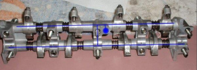
The large blue dot is where oil enters the system, this is where I normally drill or chamfer to increase oil flow and decrease sludge deposits. As you can see the rocker arm shafts channel the life of the valve train. From the exhaust shaft each cap has a cross drilled port to lubricate the cam bearings also every rocker arm has a small sprayer to squirt oil on the cam lobes. If your truck still has Hydraulic rocker arms installed each rocker arm has 4 ports, the additional ones relieve pressure from the lash adjuster which squirts out the top of the bucket, I believe it also has one which lubricates the valve springs because the dual valve springs which are used are a light interference fit. Because of the interference fit heat is generated between the springs especially at high rpms. This heat can slowly deteriorate the springs, not to mention consumes power. The holes to lubricate the springs helps cool the springs and reduce friction which will increase reliability and technically increase performance. The trained eye can see in the picture that the ports in the caps have been slightly chamfered this should be done to help lubrication, not a whole lot is required I used 90 deg chamfer bit at extremely low speed and just barely touched each one for half a second leaving a chamfer around 1/16 of an inch wide. Also if you have hydraulic rocker arms and switch to mechanical you should probably increase the size of the oil hole for the cam lobes about .001″ to .003″ of an inch to help relieve extra oil pressure caused by the fewer openings on the mechanical rockers. It would also be advisable to drill a small port to lubricate the springs. These modifications should be performed by experienced machinists and not your average beginner, DO NOT go to your hardware store and drill these with your average drill bits. Doing this runs the risk of drilling too large which could leave components without oil.
Once the oil has gone through the rocker arm assembly and has been thrown onto the cam and springs most of it settles into a valley pan type area directly underneath the cam. The oil lays in a puddle a little more than 1/4″ deep. This is enough to allow the cam lobes to slap into the oil about 1/8″ and provide extra lubrication and cooling to all the components under the valve cover. This is good and bad, it is good because it ensures the valve train is well lubricated, it is bad because it causes windage and resistance on the cam and rocker arms. Because of the way the casting of the head is made oil puddles over cylinders 1,3,4 with more oil over cylinder 3 & 4 with no oil over cylinder 2. After examining several scrap cams and monitoring the cam on my truck the lobes for cylinder 2 on the cam always had excessive amounts of wear proving that this puddle of oil is required. To optimize this on a rebuilt cylinder head a small amount of epoxy can be added between the head bolt and the outside wall of casting on the exhaust side between cylinders 2 & 3 (I’ll have a picture later because that sounds confusing). Because of the angle of the engine I also add a small rounded groove in the wall that makes the barrier near the far rear oil return. This fixes the wear problems on cylinder 2 in the cam and relieves the excess oil on cylinder 4 which perfectly evens out the system.
Leave a Reply