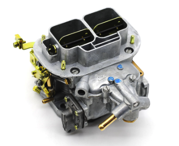
How to Tune your Weber Carburetor Video
GENERAL GUIDELINES
It is important to verify all linkage and levers are installed without binding and the linkage opens to full throttle and closes to the Idle Speed Screw. The number one and two reasons for tuning errors are improper linkage installations and over tightened linkage nut, causing a binding in the linkage assembly.
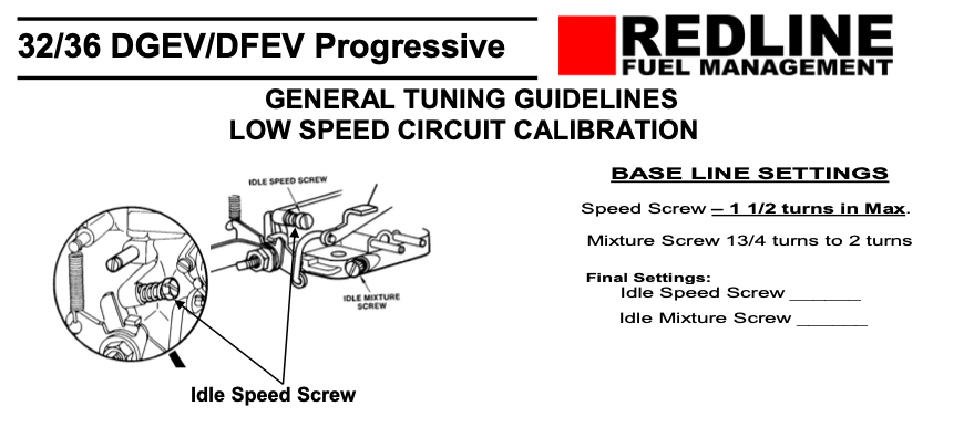
BASE LINE SETTINGS Speed Screw – 1 1/2 turns in Max. Mixture Screw 13/4 turns to 2 turns.
All settings are done with engine warmed up so that the choke is fully opened and disengaged.
Back out the Idle Speed Screw until it does not touch the throttle lever. Cycle or Snap the linkage again to be sure that the linkage and lever comes to complete close. (Checking for linkage bind) Turn in the idle speed screw until it contacts the throttle lever, then continue to turn the idle speed screw in 1 1/2-turn maximum.
Set the Idle Mixture Screw by turning it in until it lightly seats. Then back out the mixture screw 1 3/4 full turns out. DO NOT FORCE THE MIXTURE SCREW, AS THIS WILL CAUSE DAMAGE TO THE SCREW AND Its SEAT IN THE BODY OF CARBURETOR.
With the engine at operating temperature, choke fully open and engine running, turn in the mixture screw until the engine starts to run worse, then back out the screw (recommend 1⁄4 turn at a time) until the engine picks up speed and/or begins to smooth out. Back out 1/4 turn more, or until the screw does nothing or runs worse then turn back to the point where it ran its best. We are looking for the Lean Best Idle or the “sweet spot”.
Recheck timing and vacuum hook ups. Then, recheck mixture screws to lean best idle again. If all is still the sweet, best and smoothest idle then confirm and note the final settings.
If the mixture screw is out more than 2 turns, then the Idle jet is too lean (too small). If the mixture screw is out 1 1/2 of a turns or less, then the Idle jet is too rich (too large).
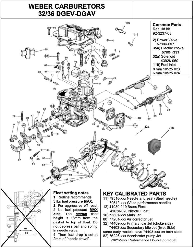
These assumptions are based on the fact that the Idle Speed Screw is not more than 11/2 turns in. If the Idle Speed Screw has to be opened more than 1 1/2 turns then this is also an indication of a lean condition usually requiring jet change. “At times” it may appear to be showing signs of richness or flooding this could also be the fuel level is too high in the float bowl. Set the plastic float 18mm from gasket surface to the tip of the float not depressing the ball & spring in the needle valve. Then the float drop is set to 2mm of “needle” travel.
SPECIAL NOTE:
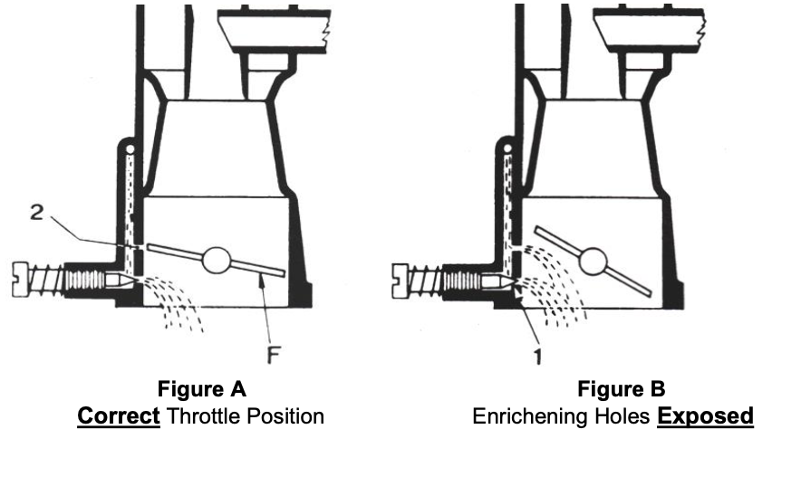
The following describes the importance of having the Throttle Plate(s) below the fuel enrichening progression holes that are drilled in the throat of the carburetor.
Progressive Carburetors: 32/36, DGV, DGAV, DGEV, DFAV, DFEV etc.
Shown in Figure “A”, the idle speed screw isn’t turned in more than 1 1⁄2 turns. The throttle plate (F) is below the enrichening progression holes (2), the carburetor would be at “curb” idle.
Also, there would be zero vacuum at the distributor “ported” vacuum source
GENERAL GUIDELINES
Shown in Figure “B”, the idle speed screw IS more than 1 1⁄2 turns in. The throttle plate IS exposing the enrichening progression holes. Also, you would have vacuum at the distributor “ported” vacuum source. The extra fuel at curb idle, from the exposed enrichening holes, is 95% of the tuning problems we experience. The Idle Speed Screw CAN NOT be turned in more than 1 1⁄2 turns MAXIMUM, or, you will experience a rich idle condition, a stumble of idle and at around 1800 RPM.
GENERAL TUNING GUIDELINES MAIN CIRCUIT CALIBRATION
Low Speed Circuit:
The Weber low speed-idle jets are responsible for all calibrations and driving events from idle threw 2200 RPM. The low speed circuit does effect the main circuit calibration. The low speed circuit is always where we start “jetting”. After calibration for the low speed circuit is complete, we continue with the main circuit entry, timing overlap and power starting around 1800 RPM threw 2200 RPM.
Main Circuit:
Without a way to measure power output or speed changes (dynamometer, timed speed runs etc.), we rely upon “bracketing” to confirm main jet calibration. First write down your starting jet sizes. Then we would increase the main fuel jet in 1⁄2 size increments. Each 1⁄2 jet size change should be noted and how much it “seemed” to change the performance. (Each change would be, maximum RPM increase or decrease, power increase or decrease, RPM & conditions of hesitations, bogs, or flat spots, what RPM do they occur?) We do this until our changes do not seem to improve the performance. Then we reduce the jet size back to where it seemed to have the most improvement. (Bracket) We then add one size air jet, and note how much it “seemed” to change the performance. If our performance has increased we would continue to increase air jet sizes until performance stops improving or decreases. Then we reduce the jet size back to where it seemed to have the most improvement. (Bracket) If our performance has decreased when we changed to a larger air jet we would, logically, decrease the air jet size until the performance stops improving or decreases. (Bracket)
Occasionally a slight “transitional” hesitation is experienced. This would be at the end of the low speed circuit to the beginning of the main circuit, the timing overlap RPM usually around 1800-2200 RPM. Should you experience this transitional stutter or hesitation, this is probably/usually a lean transition from the low speed circuit to the main circuit, (timing overlap), using the next size smaller size air jet may tip in the main circuit sooner. Or, the next 1⁄2 size larger main jet may tip in the main circuit sooner, Or, a 1⁄2 size larger idle jet will enrichen the low speed circuit, holding out the “transitional” overlap to a higher RPM. Slightly increasing or decreasing the fuel height in the fuel bowl (fuel height around the emulsion tube) will also “tip in” or “hold out” the main circuit. Any one of these options has a price, more fuel consumption.
Simple Basic Rules to Remember:
Three air jet size changes (increase lean) (decrease rich) are equal to one fuel jet size change.
When altitude is increased you will need to increase the air jet over the fuel jet. Commonly, this is done just the opposite, reducing the fuel jet and the result is less power.
When there is an increase in venturi size you will commonly increase main jet size, conversely, if you drop venturi size you will drop main jet size.
Emulsion tubes are not changed in the normal course of calibration like idle jets, main jets or air jets. Emulsion tubes require much more deliberate thought.
Watch this detailed YouTube Video here

Leave a Reply