Machine Work
For anybody wanting to have a rebuild that lasts a long time taking it to a good machine shop is a must. Sure if you want to wing it you can possibly just replace the bearings, rings, gaskets, etc. and just slap it back together but don’t expect it to last long. Since mistakes and poor equipment don’t make good race engines speed shops are usually the best place to work to have machine work done but you still get what you pay for so a speed shop will probably be more expensive. Occasionally you will find a really good machine shop that will do the work relatively cheap, this is because they usually have a large reputation and customer base which lets them make their money in pure volume. Make sure you know what you’re talking about though because if you sound like a idiot you’re not as likely to get good work and if they can’t understand you to know what you’re going for they can’t use their judgement to do what is best for your build. So for some basic terminology if you are talking about measurements:
.500″ is not half an inch it is “Five Hundred Thousandths”, it is also not “Five Tenths” .005″ is read “Five Thousandths”
.0001 is read “One Tenth” (Tenth of a Thousandth, not Tenth of an Inch)
So if you want your bearing clearance to be .0012″ for example you would tell the machine shop to machine the crank for a clearance of “One and Two Tenths”. If you want or need the cylinders to be bored larger this is done in .010″ increments. If you wanted the cylinders bored .030″ larger you can tell them “Thirty Thousandths Over”, or just say “Thirty Over”. If you don’t know what you want the cylinders bored to you can just tell them bore them to whatever it takes to clean them up. If you tell the shop you want the block machined “Point Zero Three” they are going to look at you like a moron.
This being said machining the top of the block is called Decking. Machining the head flat is usually called Shaving, all overhead cam designed heads should be straightened before they are shaved for flatness. Machining the main caps where your crank bearings are going to go is line honing and is done to make sure all the bearings will be in perfect alignment for the crank.
Typically, when you take an engine to a machine shop the short block will either be assembled or you will take all the parts needed for them to do their work (even if they won’t be machining them). Since most people reading this will be taking in a used engine for rebuild the shop would tear down the block if need be then hot tank it and possibly some of the other parts. The hot tank is basically a big industrial dish washer with a caustic soda solution in it that heats and blasts most oil, sludge, and deposits off the parts. For parts with heavy deposits or carbon they will then be descaled to get them perfectly clean. After cleaning magnetic parts such as the crank, rods, and sometimes block will get magnefluxed to check for cracks. Some aluminum parts may be checked using Zyglo. Most of the critical parts will get a visual inspection and be measured for tolerances. The cylinders will be measured for bore size and taper and usually machined to the nearest .010″ needed for them to be perfect and later will be honed. It is recommended to have the shop order pistons or provide pistons yourself for the size of bore needed, this way the machine shop can custom machine the cylinders to the pistons. If you are going to be installing forged pistons having the shop match the clearances will be required because forged pistons expand differently from the stock cast pistons. Failure to do this may cause the piston skirt to expand into the cylinder wall and destroy it or you may break piston rings or have low compression. The deck will be checked for straightness and rust or pitting. If the deck it not straight that is usually a sign of a serious problem and will be recommended to replace. Decking is usually done to fix rust pitting, surface finish, or to increase compression. Main caps will be installed and checked for alignment and size, if they are out of spec they will be machined.
For those taking who will take apart the block before sending it to the machine shop it is a good idea to take pipe brushes and run them down the oil and coolant passageways with some engine degreaser to free up any sludge or scale which could be built up within. Same goes for the crankshaft. Doing this before hot tanking is added benefit to not only have a perfectly clean block when you get it back but also is an extra cleaning step to make sure there are no bristles from the brush left in the engine.
Machine work on the crank can be very involved since it will not only be checked for cracks but the main journals and rod journals may be machined as well as other modifications and balancing. Just like with the pistons for the machine shop to turn the journals down to match the bearing clearances they will need the bearings as well as the block and connecting rods since the clearances would have to be measured with the bearings assembled. If you are going to have the crank balanced they will need the entire rotational assembly which includes the Harmonic balancer, connecting rods, wrist pins and locks, pistons, piston rings, flywheel, and sometimes the clutch.
One thing that I highly advise on all engines whether they are for performance or not is to lightly grind out the rough casting that you can. The main purpose of this is to release core sand trapped in the metal during casting. This would be considered part of engine prep but I advise doing it before sending the block to be hot tanked, this way you are absolutely sure that any debris left in the block is washed out and it will help release any additional core sand left in the open pores. This will be done mostly in the crank case and maybe some of the oil passages and coolant passages if you can work your way in those areas. To do this take a grinding wheel/drum and a die grinder and carefully move back and forth over the cast areas. Your aim is not to grind the surface smooth but just get most of the cruddy stuff out. If you see spots that look like slag built up over the surface get those completely out as they will contain a lot of core sand and sometimes chunks will flake off. Also gently smooth out any sharp edges such as cast seams and casting flash since these are stress risers. Removing stress risers will increase the strength and reduce chances of cracking. Unless there are stress risers on the mains do not touch them. Even though the oil will go through the oil filter before getting to any critical parts very small particles of sand will make it through and over the life of the engine cause additional engine wear. Other advantages are a possible increase in life on your water pump and especially the oil pump since it sees unfiltered oil.
Engine Prep
At this point you should have all the parts back from the machine shop and you need to do any prep work remaining before assembling the block.
It is easier to build an engine with more power at low rpm that will hold together than it is to build a lesser power engine that revs higher. That being said special attention needs to be taken to everything on any performance build, including tighter clearances in most places the higher you want to go in rpm. Cam and crank journals like the one below should be polished. Often this is done at the machine shop if it is machined. Micro scratches like this catch oil and increase resistance, they also increase the possibility of metal to metal contact in a low oil pressure situation or when starting the engine. Journal surfaces should be polished with 600 grit sandpaper first moving the paper like you would polish a shoe. After 600 grit you should use 1000 grit or higher to get an almost mirror image.
Before starting on assembling any parts take the block and blow it out thoroughly with compressed air. It would be advisable to run the pipe brushes through again or at this time if you have not done so already. Sometimes debris or caustic soda residue can be left in the passageways. After going through all the passages again blow them out with compressed air on both ends several times to work free anything that might get lodged.
Ok, you have all your parts back from the machine shop and your journals are matched to the bearings you provided or the shop ordered for you. Inspect all the bearings making sure there are no nicks that can be felt with your fingernail on any of the surfaces. If the bearings have been damaged due to bad handling, you don’t really have many options. You can call up the machine shop and “express your discontent”, you can buy a new set of bearings and try to match up clearances the best you can, or you can take some white scotch brite or 1,000 grit sand paper and try to burnish and polish the defects out. The last is not all that bad on most low power street engines. If you are building an engine that is turbocharged or may see some aggressive running you will probably want to go as far as you can with the first two options.
Crank & Bearing Assembly
Clean all parts to be assembled with solvent. Rubber gloves would be helpful but will often swell and fall apart when exposed to paint thinner and other solvents so it is ok to use your bare hands if your careful. The bearing surface on the mains must be perfectly clean, free of all lint, and even finger prints. After the final cleaning do not touch any mating surfaces, dirt and finger prints behind the bearing when it is assembled will cause it to deflect and cause permanent damage when the engine is fired. Clean the bearings carefully holding them from the edges so you don’t get any fingerprints on the backing or bearing surface. If the bearings are labeled for position with marker make sure you don’t lose track to where each bearing needs to go.
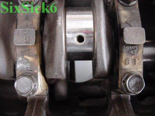
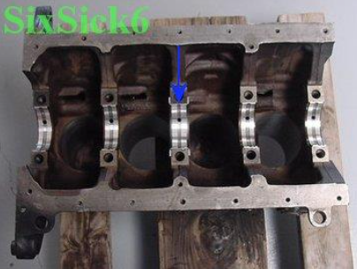
Install the proper bearing halves into the block dry. These are usually the halves with holes in them for oiling, there is to be no oil, assembly lube, fingerprints, or anything on the bearings when you install them, the back of the bearing surface is not supposed to move and should not be lubricated doing so will deflect the bearing causing it to spin or cause engine damage when you fire it up. Because of this I recommend using gloves at this point. When installing insert, the bearing tang in the bearing groove holding it level with the block or cap surface, roll it down into the bearing and press the opposite half in. Make sure the bearing is properly centered and each end is as level with the machined surface as possible. Make sure oiling holes are perfectly aligned.
Take note that blue arrow is pointing to the thrust bearing, this is what controls the crank from moving forward and backwards.
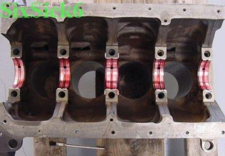
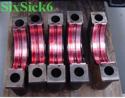
Next do the same with the main caps. When the block and cap shells are installed you can now apply assembly lube on the bearing surfaces, don’t wimp out on smearing it on there as it is the life of the engine until it is broke in.
Gently position the crank over the block and set it straight down onto the bearings and place the caps in their marked positions. Take note they must not only go in their proper place but also be facing toward the front of the engine as marked. Take a dead blow hammer and carefully tap each side of the cap in keeping it as even as possible so it does not bind. If you have a cap girdle put it in place at this time. Insert the bolts and torque the first cap down to the first 20 lb/ft step and check to make sure the crank rotates. Go to the next cap in sequence, torque, rotate and repeat for the remaining caps. If at any time you torque a cap and the crank doesn’t rotate easily afterwards there is something with the installation on that cap. Remove it, verify the bearings and cap are installed properly, re-install and check until it is right. When you have torqued all the caps down at their first step and everything checks ok finish torqueing down the caps in sequence at about 20 lb/ft steps until fully torqued.
Piston Assembly
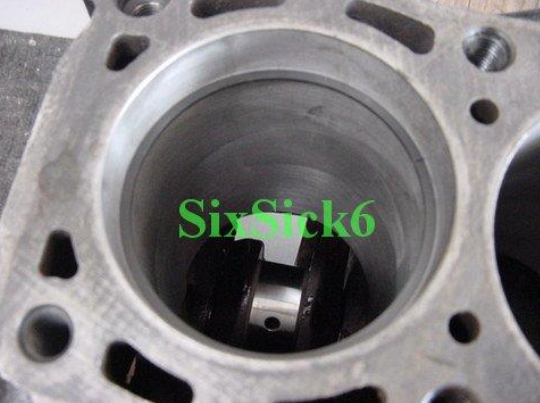
At the machine shop they should have bored and honed your cylinders for the proper clearance you need for your pistons. Many engines will have pistons designed to run incertain cylinder locations but Mazda was not that picky when designing their parts. If the machine shop didn’t machine the bores to match the pistons take a T-gauge or dial bore gauge and measure your bore sizes, then take a pair of micrometers (or at least calipers) measure your piston sizes and try to match them to the cylinder that will give you the best tolerance. Once you have them figured out number them with marker to make sure they get installed in the right cylinders. The actual piston-to-cylinder clearance you want will depend on the type of build you are doing. Stock recommendation is .0015″-.003″ but tighter is not always better. On a turbo application for instance you may want to set your clearance closer to .003″ since the extra heat will cause more expansion in the piston.
Inspection
Time to assemble the ring package onto the piston. Special care must be taken with the rings just like all other engine parts, this is a given but there will still be those out there who will slop them together, think they did good, then claim the engine was poorly designed when it doesn’t last or burns oil when really they just did a crappy job building the engine. Many people also assume new parts are perfect and ready to slap into the engine without bothering to inspect them for defects or proper fit. During a previous position I held in an engine shop it was my responsibility to inspect all of the piston rings for the engines we raced every weekend. Short of F1 these were supposed to be the best piston rings you could get and it was not uncommon to reject 10-50% of the rings brand new right out of the box.
Before installing the rings, you need to inspect and prep them. The oil ring is actually 3 pieces, a spacer and two support rails. When checking the oil ring and rails make sure they are not damaged in any way, especially the wavy spacer ring. You will also have a scraper ring and compression ring, visually inspect them for rust, cracks, or burrs. If the ring is marked or stamped like below clean off the mark or take a wheat stone and remove the burrs we don’t want them to cause sticking or micro welding of the ring to the piston which may cause power losses later. Be pickier with the compression ring, which fits in the top of the piston, it is under direct stress of combustion and will see the most abuse. If the ring is not fixable do not use it, some builders will buy two sets and use only the best of each.
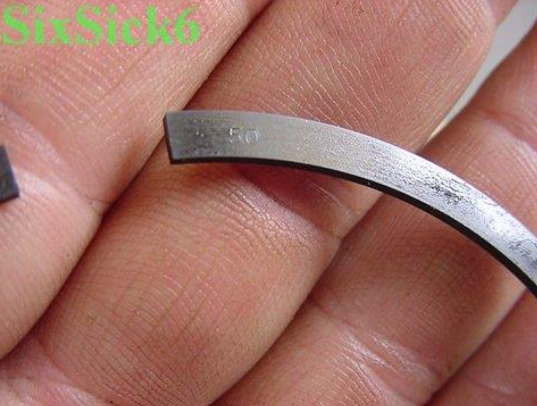
Setting Ring Gap
Before installing the rings, we need to gap all of them except the oil spacer this needs to be done because as the engine is running they will heat up and expand. If the rings have too much gap, there will be a lack of compression and the engine will constantly burn oil. If the ring gap is too tight the ring will need more room to expand than what it has and it will seize in the cylinder.
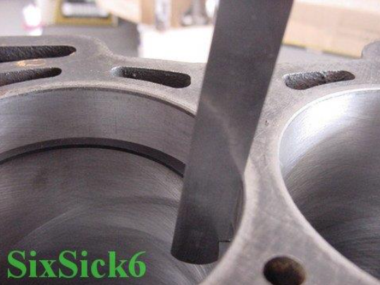
To gap each ring, you will need to slide it into the cylinder bore in which it will be finally installed in. Carefully insert a piston upside down to make sure the ring is square in the bore and the ring tips are flush. Avoid handling the rings too much before doing this or while measuring the gap, your body temperature will heat the ring and throw off your measurements. Take some feeler gauges and measure the gap in the ring. Compare this with the factory manual to determine how much needs to be filed off. Many people use the specs provided with the pistons or rings, this is generally not recommended because they usually provide a very conservative number that will likely result in oil burning and lack of compression. The exception to this is when buying pistons or rings from a performance company, in this case the company will know the materials used in their product and what the best ring gap is for your exact application. Remember to keep track of the ring because it must be installed in the same cylinder you gapped it in. Below are the Mazda recommended ring gaps for the F2 engine in the B2200.
Factory Ring Gaps
Top Ring: .008″-.014″
Second Ring: .006″-.012″
Oil Rail: .008″-.028″
When using the specs above keep in mind the rebuild you are doing. If you are using over-sized rings there will be more material to expand and a slightly larger gap will be needed. For high heat applications like running a turbo you should also run a slightly larger ring gap because the heat causes more thermal expansion. I like to use the smallest recommended ring gap for original size pistons and add .002″ of gap for every .020″ (.5mm) of oversize, perhaps a little more for a turbo application.
Finally, we can install the rings on the piston, this is best done with ring expanders but can be done with your hands if your careful. When using a ring expander spread the ring as little as possible to install it. When installing by hand you want to keep the ring as straight as possible and not stress it.
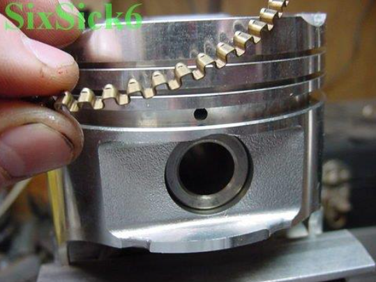
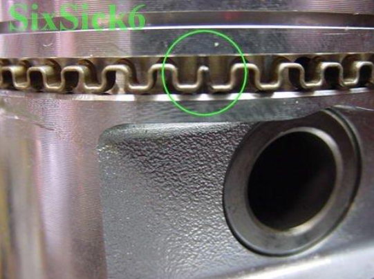
The oil expander shown above must be installed first because it is on the bottom and the rails are held away from the piston by raised bumps on the inside diameter. The picture below shows the ring tips on the spacer ring after it has been installed. These both need to be facing the same direction, if they are not the ring is defective and shouldn’t be ran since it will not have the right spring tension and may dig into the rails.
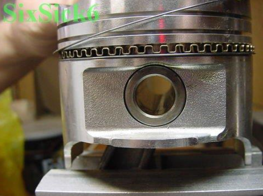
Now you can install the rails making sure they properly seat on the oil expander.
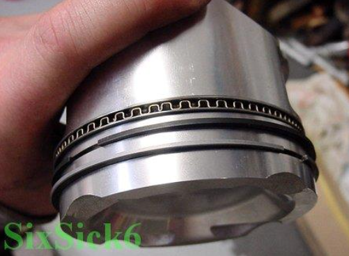
Next to install is the scraper ring which is the one above the oil ring you just installed. This ring does have a top and bottom which should be marked or identifiable according to the ring packaging. If it has a napier cut along the outside edge this should face the bottom of the piston. Last is the compression ring, this may or may not have a top and bottom. Before installing the piston assembly in to the block stagger the rings 120 degrees apart from each other. The rails on the oil ring should also be staggered, obviously if the gaps lined up the rings wouldn’t seal, rub the cylinder walls down with a film of engine oil before installing.
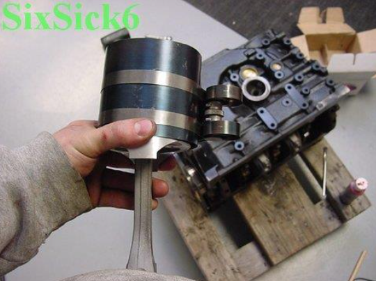
To install the pistons, you will need either a ring compressor or a tapered ring like the ones ARP make both shown below. You will also need some stiff hose to slide over the rod bolts to guide them around the crank journals and not scratch anything. When using the ring compressor, it needs to be tight enough for the rings not to hang up on the cylinder and loose enough to slide smoothly to install. Some people prefer using a dial bore gauge to assist them in making sure the rings will slide in. When ordering an ARP type installer, the rings are made precisely to the bore size you are installing for.
You are not to use anything other than your hands to install the pistons in the bore period!!! If your Haynes, Porsche Factory Manual, or buddy next door say to use the handle of a hammer or block of wood to tap them in they are WRONG!! There are three or four huge reasons why you don’t hit the piston with anything including your hand while installing them. First off if your installer is too loose you’ll smash the oil ring as it catches on the block, second the jarring motion may bind or damage the rings. Aluminum is very soft so you can also damage the face of the piston by hitting them. Slide the rod and piston into the cylinder until the ring compressor is against the deck. Hold your fingers around the outside of the installer and put your thumbs on the center of the piston, kind of like making a clay pot in grade school. Swift and gently slide the piston into the bore, if it hangs up do not hit it, simply take it back out adjust the compressor a little tighter and try again.
Once you get a piston installed align the rod onto the journal and hand tighten the cap on. Take a feeler gauge that is slightly smaller than your clearance and put it between the rod and the crank, this is to prevent the rod from twisting when you torque it which could nick or deflect the bearings. When you are ready torque the cap in 3 steps to full torque, spin the crankshaft clockwise once or twice to make sure it spins ok.
Leave a Reply